Get Rid of Snorers

A snore alarm electronic device
Here I describe a little electronic device that detects snoring.
The principle though very simple is efficient and well protected against false triggerings.
Upon detection, it generates a noisy and painfull alarm.
Just what's necessary to wake up everybody except the snorer.

Device

The Principle
Breathe is a repetitive phenomenon. Moments of silence and noise repeat.
Detection of snoring is based on the recognition of the cycle silence-snoring.
Duration of each silence is compared to the duration of the previous silence.
Duration of each noise is compared to the duration of the previous noise.
The precision of the periodicity of the cycle as well as the number of successive cycles
necessary to trigger the alarm can be configured by use of jumpers connected to the input port of a microcontroller.

Design
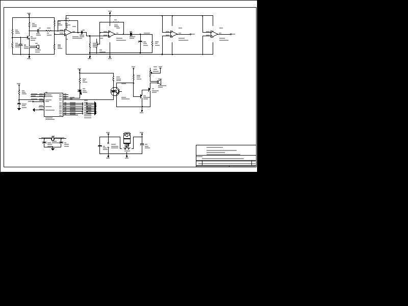
Schematics

Schematics
CAD files

Printed Circuit Board
Here is the Whole package file containing...
ORCAD Schematics file
ORCAD Components Libraries for the schematic and the PCB
ORCAD Schematic printout in HPGL and PostScript formats
Layout printout in PostScript and Acrobat formats
Assembly Source Code File, HEX file for the microcontroller and related files.

User's Manual
The Led has two functions:
On start-up, it flashes 4 times per second for 5 second. This is to verify visualy proper startup and it also gives the time to the analog circuits to stabilize their outputs.
Then it reflects the computed output of the digital low pass filter. Off when there is noise, On in the silence.
Two potentiometers are accessible.
R19, on the right side of the board, controls the sound level of the tweeter. One increase sound level by turning clockwise. To tune the volume, put a jumper in front of B[7] to go in volume tune mode.
R22, middle left, controls the final gain of the analog amplifier, that is to say the sensitivity of the device to noise.
One Increase sensitivity by turning clockwise.
At middle course, a long liner airplane flying at 10000 feets makes enough noise to switch off the led.
On power up, a timer is reset and starts to count.
The device is active only for the first two hours and after six hours.
If the alarm triggers after fourteen hours, it means that a new night started and the timer is reset.
This is to avoid alarms right in the middle of the night.
The user can chose among few configurations by placing jumpers around the microcontroller.
 ST62E10 CPU ports
Jumpers Configurations:
0 when Jumper is In. 1 when Out
- B[2].B[1] (JP2,JP1) Maximum admitted duration ratios
[00] == 25% , [01] == 35%, [10] == 45%, [11] == 55%
- B[4].B[3] (JP4,JP3) Tone of alarm
Not used anymore by the software
- B[5] (JP5) When will alarm trigger ?
0 == after 3 identical patterns, 1 == after 6
- B[6] (JP6) Time constant of digital low pass filter
0 == 0.22s (6*36.86ms), 1 == 0.48s (13*36.86ms)
- B[7] (JP7) Mode
0 == Loud Speaker volume tune, 1 == Normal mode.
Nota : B[0] is connected to the analog amplifier output, in [0V-5V] range.
When JP6 is on, and R22 is tuned close to ambiant noise detection, false triggering can occur.
When JP6 is off, the device is well configured for the specificities of snoring.

The Board, Components Side
Here the board is configured for...
- 45% admitted duration ratios
- Trigger after 6 repeated patterns that is to say 3 breathes
- Digital Low pass filter time constant : 0.22 second
- Normal Mode
However, the optimum configuration is
- 25% admitted duration ratios
- Trigger after 6 repeated patterns that is to say 3 breathes
- Digital Low pass filter time constant : 0.48 second
- Normal Mode

Solder Side
Comments
There are two discrepancies between the CAD files and the pictures.
CAD Files are correct and take into account the following modifications.
A resistor R23 of 1 Mega Ohms was added behind the diode D3.
A pull-up resistor R24 of 10 Kilo Ohms was added on the base of the transistor Q3.
They appear on the bottom picture.
I can't remember why I put the outputs of two op amps to VCC. Probably a mistake.
So If you don't feel confident with that, just don't put the strap located between C6 and R1 (a 10K resistor connected to pin 7 of the ST6210).
Notice that the tweeter is directly powered by the power supply VDD, not by the regulated output at 6Volts.

Technical Characteristics
 Size : 126mm x 45mm x 23mm (height)
 Energy : Standard universal power supply. 8.5 Volts to 20 Volts
 Processor : 8 bits microcontroler ST62E10 or ST62E20 (thomson).
 EPROM 2Kbytes. Source Code size about 15 kilobytes.
 RAM : 64 bytes !
 Processing Power : About 6.5 microseconds per instruction.
 CPU load : close to 0 %.
 Microphone Electret polarized, amplified 10000+ times connected to an ADC input
 Digital low pass filter with long time constant.
 Sound level measured 27 times per second.
 One Red Led under software control, weakly lightened for gentle view in the night.
 Tweeter under microprocessor control by one digital output
Design Date January 1993.
Comments, Questions ? Ask me at 
Back to "ideas"
Reach the top


 ST62E10 CPU ports


